
Robomasters: Gimbals

During my time at Texas A&M, I competed in an international robotics competition called RoboMasters. In this event, teams build and pilot FPV-controlled robots that battle by firing hard plastic balls at pressure plates mounted on opposing robots. Each team designs multiple robot types, but most feature a shooter head (where the FPV camera is located) mounted on a two-axis gimbal and connected to an omnidirectional drive train. I was primarily responsible for designing the gimbals, though I also contributed to systems related to the shooter head.
Gimbal Design
Before getting into the various iterations of gimbal mechanism I designed, I will first summarize the constraints and performance metrics which drove my design decisions throughout this process. My hope is these provide context for decisions I made throughout my iterations on this mechanism.
Constraints:
-
Must traverse shooter head in pitch and yaw axis
-
Must infinitely rotate in the yaw axis
-
Must rotate shooter 45 degrees above the horizon and 35 degrees below horizon in the pitch axis
-
-
Must have no discernable backlash in both motion axis
-
Must drive yaw and pitch axis with reasonable angular acceleration and velocity
-
Must utilize DJI closed loop servo motors
-
Must adhere to the full robot size constraint
-
Must pass power and signal wiring from robot base to shooter head
-
Must not catastrophically fail during normal match
Performance Metrics:
-
Size (X" x Y" x Z" measurements)
-
Mass (kg)
-
Maintainability (hrs maintenance per hr of operation)
-
Reliability (% matches lost due to gimbal failure)
-
Manufacturing cost (dollars per unit)
-
Manufacturing complexity (man hours per unit)
Early CAD Prototype Model


This is a prototype model which was never physically built. It was my first attempt at this mechanism and it had several issues which were addressed in the next iteration. This mechanism's timing belt tensioner is not very robust, it doesn't have clean mounting points, and its a bit large.
First Physical Prototype


This assembly is the first build yaw axis prototype, and was never integrated into a full robot assembly. Unlike the previous CAD prototype, it uses a pair of brushless servos rather than one. This mechanism had a number of issues which can be seen below:
-
The belt tensioner slips over time
-
The assembly is too large
-
The assembly has a high part count. In particular there are additional plates for securing the large radial ball bearing that are unnecessary.
First Integrated Gimbal Assembly


This is the first integrated gimbal yaw unit. This assembly was configurable, and ended up being adopted by many robot platforms. To address the issues of the prototype the following changes were made.
-
The smaller pulleys were shifted to the top of the servos, allowing both the smaller and larger pulleys to have a smaller diameter. This dramatically reduced the assemblies size and weight.
-
The belt tensioner was changed to a mild steel cam assembly
-
Many unnecessary parts were removed including the plates capturing the bearings
This assembly had some issues, but preformed very well in competition. Some of the issues are listed below.
-
The inclusion of the needle thrust bearing in this assembly is unnecessary. The radial bearings selected were relatively large to accommodate the slip ring on their inner diameter, and their load ratings (both radial and axial) significantly exceeded the loads present in this mechanism.
-
The pulley shield was unnecessarily difficult to make
-
The tensioner worked well, but was complex and difficult to adjust
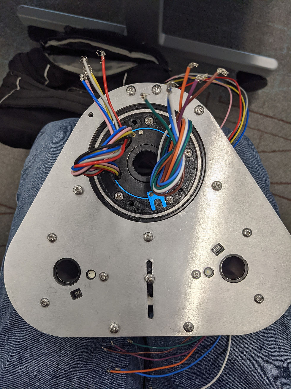
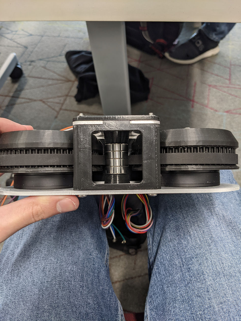
Second Integrated Gimbal Assembly


Unfortunately, the only physical images of this gimbal I could find are close-ups in a half assembled state. That being said, the assembly was a significant improvement over the previous iteration. The following changes were made:
-
The needle bearing was removed.
-
The pulley cover was changed to a 3D printed part.
-
Instead of using a complex cam system to lock the pulley tensioner in place, a simple slot was used with oversized bolts.
-
The yaw axis 3D printed housing was made rectangular. This is less space efficient than the original shape, but is easier for others to integrate and work around.
Some of the issues with this assembly were:
-
A space conflict between the U-bracket (structure holding the shooter head) side cover and the vision computer mounted there.
-
The pitch axis hard stops were difficult to access.
Balancing Standard Gimbal Assembly


This is a gimbal unit I designed for the Texas Aimbots balancing standard project. This robot used a unique drivetrain called collinear mecanum, where the robot balances on four collinearly mounted mecanum wheels. It essentially is a segway style drivetrain except it can also strafe side to side.
This particular gimbal was fully SLS 3D printed during my time working at Formlabs. It also has a linkage style pitch drive, which allowed the servo to be mounted lower and inside the U-bracket. The linkage components were manually machined out of aluminum on A&M's Bridgeport style machines.
It had a few interesting issues, which are below:
-
The sintered nylon material the SLS components were made from is dense and brittle, some pieces of the components actually broke off. This is not the ideal material for this assembly, even if it does look cool.
-
The design freedom of SLS 3D printed tempted me to make components with more complexity than is warranted.
-
Clearance for wiring and electronics was too tight.
-
There was some backlash in the pitch linkage due to sloppy bearing fits. This was fixed with shims.